


I have been hardwiring radars for years. I know how to get a power and a ground. I'm working on the mute button and led alert. The Phone wires that we use have 4 colors. Green is ground. Red is 12v. If you're interested in helping me with yellow vs. black, or you are interested in learning what I've discovered so far... read on! Thanks in advance.
I own an Audi. I found an OEM switch that will serve as a momentary switch for the mute button on my radar unit. I have relocated my remote display and smart cord to my alternate vehicle. I'm determined to make my OEM switch provide both the visible alert, and serve as a mute switch.
I have a Passport x50 and love it. I borrowed a V1 for a weekend and found that it eliminates a few false alarms. Especially in PA turnpike toll booths! But this isn't a debate on which radar unit is best. I need to pass along some info, and I hope to get some assistance from you guys in return.?! I'm going to go over the entire situation. B/C the more info the better, when troubleshooting.
Hook up the phone cord to the radar unit and cut the other end off. You'll have 4 wires. green, red, black, yellow.
-green is ground.
-red is 12v.
-yellow.
-black.
People are always talking 12v and ground, but nobody ever thinks about the yellow and black. I've searched high and low on this forum.
After researching a bit on some Audi sites, and doing some trial and error experiments.... yellow and black are data1 and data2. I don't know which is what. What I'm thinking... remote data2 is for the mute button. I'm guessing it's yellow. And to put myself on the line again, I'm thinking that black is remote data1 which would be a signal to turn on the led light in a remote display, issuing a warning light.
So my theory would mean that the yellow and black are one way wires. one is going out from the radar (triggering the led light). one is coming into the radar unit (telling it to mute the audio).
Photos sort of explains what I'm talking about.
However, these are for reference purposes.
These pin layouts above don't mean anything. But this is describing what the 4 wires can do. On my passport smart cord, the order of the cord is:
^However, on my plug, the hook would be on the top.
QUESTION: Does anyone have any input on the black/yellow wires, and the illumination issue for a switch. Not giving in constant 12v.
Thanks in advance. I hope this helps and I hope I get some help.
Audi specific switch info:
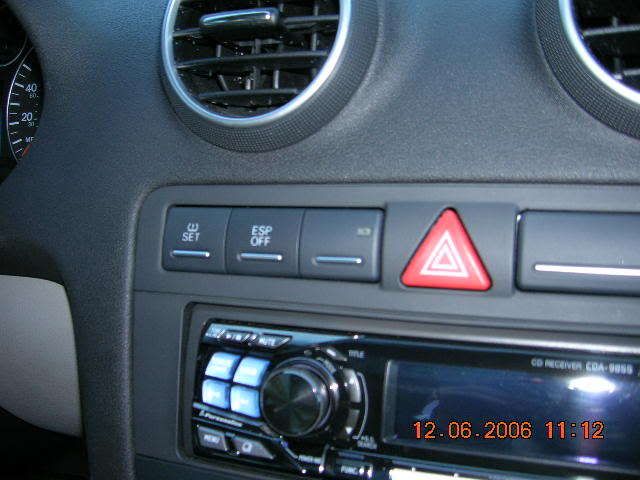
An Image of the switch in my car, taken today:
I had to remove the airbag light/switch from the console. Pull the radio out a few inches, hide the airbag switch down there, b/c if you unplug it, it'll display the airbag warning in your instrument panel.
On the back of the OEM switch you'll find 6 pins.
3 across the top, 1,2,3. 3 across the bottom, 4,5,6. The switch that I ordered has 4 wires, already plugged into the PINS you'll need to use.
1: terminal 58s. for use with dimmer, dims the switch illumination. UNUSED.
2: constant 12v for the illumination.
3: ground for illumination.
4: ground side of switch.
5: normally closed contact (for when the switch is turned off). **UNUSED for momentary contact/mute type needs.
6: normally open contact (for when the switch is turned on).
I have a Passport X50. This info is a combination of with what I learned on AW for the V1, + my own trial and errorread on.
-green is ground. ground it, and attach to PIN3.
either make your own ground, or get one from ESP switch ground wire.
-red is 12v. tie in with a power line from your fuse box. or to ESP gray/blue, to borrow power. When I run this direct to PIN2, the light just stays on. We want it to alert and light up, only on a radar alert. So I will not run this power line to the switch. I'm thinking Pin2 may want to be hooked up with the yellow or black wires, which leads back to my question.
-yellow. direct to 470ohm resistor, details below*. then run wire from resistor to PIN6, run to yellow to work the mute. ****
-black. Here is my question. I think when I get the new switch, I'll run black to PIN2. To tell the switch illumination to fire up on an alert.
***I fried the circuit board in the switch between 4 and 6 pins b/c I attached the 12v to them by accident. With the Passport, you need to add a 470ohm resistor, 1/4watt. (.25 watt) in line. They are $1 at radio crap. this will make any momentary switch operate the mute function on a Passport. Not sure about the V1. A resistor is just a little tiny bug size device with a wire coming and going. Easy to tie in with wires, and just tape up. My fried switch still illuminates. So if someone wants it for decoration, or if you can re-solder on a tiny board, let me know.
Thread on switching led bulb:
The light on the switch that send the alert is green. If that bothers you, you can get a $4 kit of led lights from radio crap. and switch it via some trick soldering.
http://forums.fourtitude.com/zeropos...how&id=2616444
Here is how you tell if you have a telephone-style or network-style RJ11 cable. Hold the two ends together, metal contact side up, as if you were trying to plug them into each other. Then look at the wiring colors. On a telephone cable, each color should line up with itself on the other end. On a network cable, the colors are inverted. But if you're cutting off one end, it really doesn't matter. The colors are your answer.
|
|

|


 Reply With Quote

 , Ive got a 9855, and in my Brother's Celica sits a 9853


Bookmarks