Paint it black and hide it behind the grill, a more powerful very directional antenna is just what the Dr. ordered out here where most roads are pretty straight.Originally Posted by zerbey

|
|

|

|
|
|


Paint it black and hide it behind the grill, a more powerful very directional antenna is just what the Dr. ordered out here where most roads are pretty straight.
Look what I found looking around the web.
Here is known as the best for european photoradars detector - of course V1 (in Euro Mode - big U, Ka Guard OFF):
[ame="http://www.youtube.com/watch?v=0O9R5oBeOvk"]YouTube - v1.MOV[/ame]
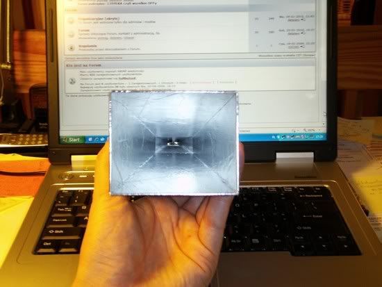
And here we have ordinary Pro78. Ordinary but with made in a simple way horn extension (carton+aluminum foil):
[ame="http://www.youtube.com/watch?v=iuA3mZBNF-s"]YouTube - Whistler.MOV[/ame]
Normally Pro78 gives 50-150m detection against such photoradar (Ramet AD9 C). Here is above 300m.
Pics of the horn:
Last edited by ; 02-23-2010 at 05:16 AM.

I don't get the comparison?
The videos show a standard unaltered short horn trouncing a detector with a homemade horn extension.
[SIGPIC][/SIGPIC]
Yes I know.
As I wrote above - Pro78 without horn extension would give only 50-150m. Since I can't show, show what I can.
I can however make the following comparison, and I think you accept that it would be quite fair:
$399 -> 450m detection
$129 (+ 30min of work) -> 310m detection
Last edited by ; 02-23-2010 at 12:35 PM.
Adding the bigger antenna will increase the gain of detector. This is similar to taking a transistor radio and sticking it inside a coil of wire. The coil of wire will cause a low sensitivity radio to pick up distant stations better.
Waveguide electronics act differently than lower frequency electronics. Think of the electronics used for microwaves as Radio Frequency plumbing. The signal act more like water in a pipe. On a radar detector the bigger antenna will increase sensitivity, but it gives the detector tunnel vision. This bigger horn is like putting blinders on a horse.
Whistler1
Basic horn antenna concept
The horn antenna may be considered as an RF transformer or impedance match between the waveguide feeder and free space which has an impedance of 377 ohms. By having a tapered or having a flared end to the waveguide the horn antenna is formed and this enables the impedance to be matched.
To achieve the maximum gain for a given aperture size, the taper should be long so that the phase of the wave-front is as nearly constant as possible across the aperture. In other words, there is a delicate balance between the aperture size, length and taper of the horn to realize maximum gain.
For ridged horns, like those used in our Radar detectors, the length of the antenna extending past the ridge is sized specifically to introduce a phase delay which is equal but opposite to the phase error introduced by the ridged portion of the horn.
So consider this before slapping a home made horn extension on your RD.
[SIGPIC][/SIGPIC]
So on a naked V985 (no plastic covers) and the modded horn butted directly against the manufactured horn, what would be the max length I should could go for (being reasonable) get the best gain? As far as tunnel vision goes I am not that concerned because until I hit the mountains there are very few curvy roads in AZ.
I have absolutely no idea!
There are formulas out there for determining the optimum dimensions of a pyramidal horn for maximum gain.........but.........these are for a specific frequency. The ridged horn is a very complex design and the length and shape of the ridge(s) greatly affect the horns broadband characteristics.
Also consider that there is already a horn in place that is optimized for broadband response and impedance matched to the specific design of the waveguide inside the detector. Putting any type of hodge podge extension on the existing horn could very well degrade performance across the entire bandwidth.
Last but not least........the front lense on many detectors may also be a specific design meant to improve the performance of the detector. It's explained a bit here.......
I'm not saying it can't be done.........it's just not something I would trifle with.The condensor lense used on the 9500i, 9500ix, 9500ci, STi-R, STI Driver and RedLine is a Plano-Convex Lense.
Radar Detectors use a compact horn antenna having a tapered wall and cavity aligned with the aperture (open end) of the horn. The Plano-Convex lense covers this aperture and introduces a phase delay, which is maximum at the center cavity of the horn and decreases towards the tapered horn walls, thereby producing a more planar (flat) wave inside the horn cavity to compensate for the deficiencies in the antenna design. It significantly increases the sensitivity and gain of the detector.
The deficiency in antenna design is due to the shortened horn which is necessary to fit into a compact detector. The lost gain or sensitivity in short horns is due to phase errors at the entrance or mouth of the antenna and in the use of sharply tapered walls within the waveguide. These errors result in higher sidelobe levels and/or less energy available for detection by the detector.
[SIGPIC][/SIGPIC]
Do you have a link to some of those equations? I can only find ones for 34ghz yagis and those are kinda small to be practicalI'd like to do some math and come up with a few small estimates on size and experiment with a few designs. A little trial and error, and accounting for known weaknesses, for what my purposes are I think it will at least be a worth while practical education and application of more advanced radar theory.
 Posting Permissions

 Reply With Quote
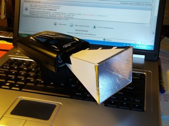


Bookmarks