Results 1 to 10 of 10
  1. #1
    Radar Fanatic
    Join Date
    Feb 2005
    Location
    Earth
    Posts
    2,357

    Default Rigging a remote mute button...signal?

    Here's a good one for you guys. I replaced the stock deck in the Accord with an aftermarket head unit, which means that I no longer have use for the audio controls on the steering wheel. As I was driving today it suddenly dawned on me how great it would be if I could use one of the buttons to mute the V1! Here's the thing: I have no idea how I would wire it.

    Does anybody know how the mute button on the remote display communicates with the V1? Is it as simple as making the voltage go high on one of the wires? Or is it something more obnoxious like a pulse train? I could always hack the remote display itself but I was hoping I can avoid it.

  2. #2
    Advanced Member
    Join Date
    Feb 2005
    Location
    Southern MA
    Posts
    10,127

    Default

    Jimbonzz would be the erson to contact since he has the computer software interface he knows how it works

    Spoiler: show

    Radar Detectors-V1 & BEL v995
    Laser Jammer-Laser Interceptor Quad
    GPS Camera Locator-Cheetah C100
    GPS Nav-Garmin nuvi w/Trapster
    CB Radio-Galaxy DX-949 w/Wilson 500
    Scanner-RS Pro-96

  3. #3
    Advanced Member
    Join Date
    Dec 2004
    Location
    Michigan
    Posts
    7,509

    Default

    Actually the voltage gets pulled low on one of the wires. Here's how it should be done:


    Jim

  4. #4
    Radar Fanatic
    Join Date
    Mar 2005
    Location
    Staffordshire, Uk
    Posts
    2,000

    Default

    there is a thing on 911 p car about a remote display which is installed in the rev counter and has a seperate mute button!

    also the guy has put switches on the remote wire so that he can turn on and off the remote display, when he turns it off the v1 display comes on!

    he has also put a off switch incase he has to turn the v1 off like when your pulled over !

    loads of pics and wiring diagrams etc...... you just run 2 wires from the mute button on the v1 remote to your steering wheel stereo controls!

    very smart install! i hope this helps


    http://p-car.com/diy/v1/remote/index.html

    http://p-car.com/diy/v1/

  5. #5

    Default

    Quote Originally Posted by jimbonzzz
    Actually the voltage gets pulled low on one of the wires. Here's how it should be done:


    Jim
    Shouldn't the resistor go on the other side of the switch, rather than to ground? It would seem that by making the connection, all that would be accomplished is a straight 12+V to the detector mute pin, and a resistor hanging off of ground. I think you need it before the switch or on the positive side of the switch to be a proper voltage divider.

  6. #6
    Radar Fanatic
    Join Date
    Feb 2005
    Location
    Earth
    Posts
    2,357

    Default

    Thanks Jim! That's exactly what I needed to know. The way they have it wired should make it much easier than I thought.

    If I'm reading this correctly it shouldn't matter what side of the switch the resistor is on. If you look at the circuit as if it were closed, all you have is a connection between the mute wire and ground with a big resistor somewhere between the two in order to keep current low. That "T" is just a momentary switch.

  7. #7
    Advanced Member
    Join Date
    Dec 2004
    Location
    Michigan
    Posts
    7,509

    Default

    Quote Originally Posted by brick
    Thanks Jim! That's exactly what I needed to know. The way they have it wired should make it much easier than I thought.

    If I'm reading this correctly it shouldn't matter what side of the switch the resistor is on. If you look at the circuit as if it were closed, all you have is a connection between the mute wire and ground with a big resistor somewhere between the two in order to keep current low. That "T" is just a momentary switch.
    Yep, it doesn't matter which side of the switch the resistor is on. In fact, technically it would still work without the resistor, and some other DIY plans on the internet actually leave it out. However, the actual V1 mute circuit in the remote display contains the resistor, so it is my opinion that it should be used...

    Jim

  8. #8

    Default

    Quote Originally Posted by jimbonzzz
    Quote Originally Posted by brick
    Thanks Jim! That's exactly what I needed to know. The way they have it wired should make it much easier than I thought.

    If I'm reading this correctly it shouldn't matter what side of the switch the resistor is on. If you look at the circuit as if it were closed, all you have is a connection between the mute wire and ground with a big resistor somewhere between the two in order to keep current low. That "T" is just a momentary switch.
    Yep, it doesn't matter which side of the switch the resistor is on. In fact, technically it would still work without the resistor, and some other DIY plans on the internet actually leave it out. However, the actual V1 mute circuit in the remote display contains the resistor, so it is my opinion that it should be used...

    Jim
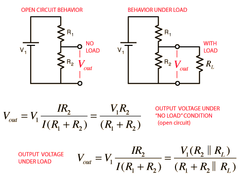
    Does it contain just one resistor? It seems like they probably would have it set up as a voltage divider since there would be no good reason to run the full 12 volts as a mute trigger, but it's possible. I haven't seen a switch drawn that way in a schematic before, but it looks like the resistor is doing nothing like it is now. If you had one prior to the switch and one prior to ground of equal value, then you'd receive 6 volts at the mute pin for instance. But, you probably already know about voltage dividers and I'm just blabbering:

    Of course, someone with a remote display could just take a multimeter to it and press the mute button and see what the voltage is.

  9. #9
    Newcomer
    Join Date
    Jul 2005
    Location
    Austin, TX
    Posts
    32

    Default

    I think inside the V1 is is just looking for current to flow, and it doesn't take much. IIRC a 47k resistor worked as well. I think it is just hooked up to an input pin on the microcontroller.

  10. #10
    Advanced Member
    Join Date
    Dec 2004
    Location
    Michigan
    Posts
    7,509

    Default

    Quote Originally Posted by erobinson
    Quote Originally Posted by jimbonzzz
    Quote Originally Posted by brick
    Thanks Jim! That's exactly what I needed to know. The way they have it wired should make it much easier than I thought.

    If I'm reading this correctly it shouldn't matter what side of the switch the resistor is on. If you look at the circuit as if it were closed, all you have is a connection between the mute wire and ground with a big resistor somewhere between the two in order to keep current low. That "T" is just a momentary switch.
    Yep, it doesn't matter which side of the switch the resistor is on. In fact, technically it would still work without the resistor, and some other DIY plans on the internet actually leave it out. However, the actual V1 mute circuit in the remote display contains the resistor, so it is my opinion that it should be used...

    Jim
    Does it contain just one resistor? It seems like they probably would have it set up as a voltage divider since there would be no good reason to run the full 12 volts as a mute trigger, but it's possible. I haven't seen a switch drawn that way in a schematic before, but it looks like the resistor is doing nothing like it is now. If you had one prior to the switch and one prior to ground of equal value, then you'd receive 6 volts at the mute pin for instance. But, you probably already know about voltage dividers and I'm just blabbering:
    Of course, someone with a remote display could just take a multimeter to it and press the mute button and see what the voltage is.
    You seem to be VERY confused for some reason.
    There is no 12V involved here, and the circuit does not actually apply voltage to any pin on the RJ-11 at all.
    The pin is normally high (5V CMOS level if I remember right, or 3V). The momentary switch pulls the mute pin on the RJ-11 low (to ground). The resistor is used as a current limiter.
    That's all there is to it.

    Jim


Similar Threads

  1. Escort 9500ci - Remote Mute Button
    By drey in forum Escort
    Replies: 11
    Last Post: 12-20-2012, 06:55 PM
  2. SRX mute remote button
    By donniesd in forum Escort
    Replies: 2
    Last Post: 09-26-2011, 03:49 PM
  3. Which aftermarket remote mute button is the best?
    By lordhawhaw in forum Valentine One
    Replies: 5
    Last Post: 06-19-2008, 10:53 AM
  4. Remote Mute Button?
    By oppa in forum Valentine One
    Replies: 26
    Last Post: 08-07-2007, 01:51 AM
  5. Remote Display & Mute button ???
    By ZeGimp in forum Valentine One
    Replies: 1
    Last Post: 06-30-2006, 06:33 PM

Bookmarks

Posting Permissions

  • You may not post new threads
  • You may not post replies
  • You may not post attachments
  • You may not edit your posts
  •