Could you do this in parallel with concealed display? OR do you have to go into concealed display and tap into mute button leads?
I have a concealed display but want a mute btn on my column wiper arm. Thanks.
|
|

|

|
|
|


Could you do this in parallel with concealed display? OR do you have to go into concealed display and tap into mute button leads?
I have a concealed display but want a mute btn on my column wiper arm. Thanks.
you could do it in parallel (as you say)...its a momentary
on (constant off) switch so it only completes the circuit
when you push the mute/switch.
fwiw Inside the remote display youll find TWO open
holes in the pcb follow the original mute button circuit/trace
wires and youll find the two holes.
when i hacked my display & removed the mute button i just
soldered some wires into these existing holes for my remote
mute button
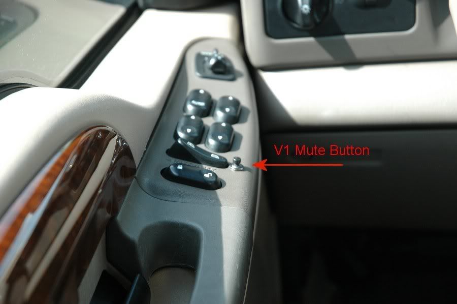
just posted some pics of my "remote mounted" mute button.
how many watts should the resistor be? 1/8, 1/4, or 1/2 watt?
wow bushpilot, nice install.

Any will work OK, since you're not dissipating much power here...Originally Posted by whiterabbit05
okie dokie. do you know which the remote display uses?
Not off hand... since it's a tiny surface mount, probably 1/16, 1/18, or 1/20 Watt. You can always go higher and be fine, I just used 1/4 just because they're common...
Keep in mind that the left-to-right ordering of the four "pins" depends on which jack you are looking at.
The pictures that jimbonzzz provided indicate "To V1 Accessory Port", which of course refers to the "accessory out" jack on the power adapters. That's fine, but unless I can tell whether the pictures are looking into the jack or looking down onto the jack from the top, it is useless. The only way that those pictures resemble anything familiar to me is if they are top-down views, and as such, they imply that at the "accessory out" jacks, the left-most pin (when looking into the jack) is the data pin. According to the drawings that Valentine's technical support people sent me a few years ago, this is wrong, and is the reverse of what is correct.
I haven't personally verified the drawings that Valentine sent me, but it seems unlikely to me that they would be incorrect, and unlike the drawings that jimbonzzz probably took from the site that he wasn't supposed to mention, the drawings that Valentine sent to me look like what you see when you look into a jack, and each of the four drawings is clearly labeled "Looking into .." I would be surprised if these drawings are incorrect, since it is apparent that whoever drew them, properly understood that in order for these sorts of drawings to be of any value whatsoever, they have to be drawn in a way so that the person looking at them will immediately recognize how to transfer the image to the actual jack.
According to the drawings that Valentine sent me, if you look into the V1's jack and ignore the two outer-most pins on that 6-pin jack, the middle four pins, from left to right, are display output (data), ground, +12V, and "Audio/mute". The Audio/mute line is normally +5V and provides the power for the Remote Audio Adapter, and it is used by the Remote Audio Adapter and the Concealed Display to signal to the V1 for engaging the mute or for mode selection. That same ordering applies to the "accessory" jack on the power adapters, and to the "power-in" jack on the Remote Audio Adapter. The reverse ordering applies to the other jacks: the "main" jack on the power adapters (or the one that has the little picture of the V1), the "power-out" jack on the Remote Audio Adapter, and the jack on the Concealed Display, where once again you ignore the two outer-most pins.
Clearly, the way that you make the remote muting switch, depends on where you want to connect it. You can use a regular telephone T-adapter, by inserting its base/prong into one of the jacks on the V1 or the accessories. You can find T-adapters that have a solitary jack on the base side instead of a prong. Manifestly, you use a length of cable to connect the base to one of the jacks, and just as when you use a T-adapter with a prong, the ordering of the pins on the two side-by-side jacks on the other side of the T-adapter, will be the same as the ordering that applies to the jack to which you have connected the base of the T-adapter. Said differently, when you use a T-adapter, you create two jacks of the type to which the base of the T-adapter is connected.
How's that for a first post?
My apologies that you are having difficulty understanding my drawing. I never claimed to be an artistBut, several other people on here have followed the drawings without difficulty. I put two views on there, which are a top view and an end view of the RJ-11 plug. I thought these drawings were very reasonable, and they are very comparable to what can be found elsewhere (including some of the VR diagrams which you praise so much!). I didn't make a diagram of a jack, since a jack isn't required to make the cable, and It *should* be pretty obvious that neither of these drwings are of a jack. But, I guess it wasn't very obvious to *you* for some reason.
The pin order in my drawings IS in fact correct, if you're plugging in to the V1 accessory port. I am well aware of the diagrams Valentine Research sends out to people. They've been posted on this board several times, and they in fact confirm that my pin order is correct:
Power Jack Summary
Remote Mute
Just what the hell are you trying to imply here? What are you accusing me of?
I didn't "take" any drawings from anyone's site!!!
Please explain what you mean!!!
Could have been better. Are all of your posts on here going to obsess on RJ-11 jacks, and accuse the admins of wrongdoing?
If so, you're not going to last very long!
 Posting Permissions

 Reply With Quote
Bookmarks